

Kinematics is the study of motion or movement in space. In the case of Linear Delta Printer Kinematics we are interested in how the (linear) motion of three carriages along identically spaced vertical columns is transformed into the movement of the tip of a hotend in the usual Cartesian system of X, Y and Z coordinates.
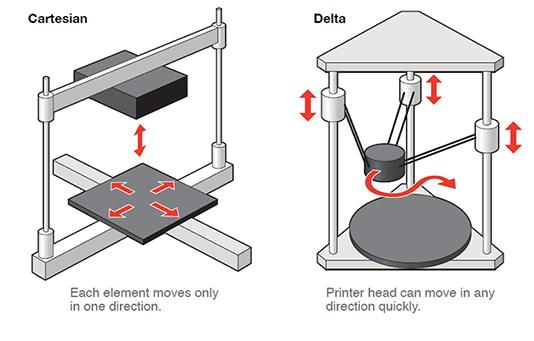
With a simple cartesian printer, the carriage mechanism moves directly along rails in each of the x, y and z directions. If you want to move a print head from the origin to, say, (10,10,20) you simply direct the motors to move it 10mm along the x axis rail, 10 along the y axis rail and 20 along the z. With a delta printer, it’s not so simple. Moving any one of the carriages which run up and down the three vertical towers will cause movement of the printer nozzle in x,y and z simultaneously. Inverse kinematic calculations are required to work out how to move all three carriages to move the print head to the given (x,y,z) coordinates.
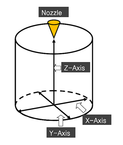
Delta Printer Coordinate system
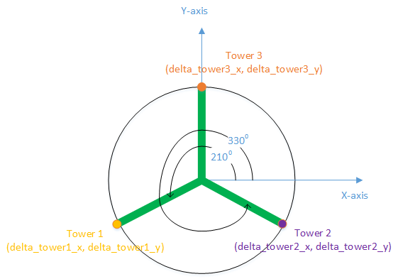
The below image shows the coordinate system used for the discussion on this page.
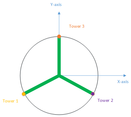
To simplify the math, let us assume that one of the three towers (tower 3) is on the Y-axis. Tower 1 is front-left and tower2 is front-right. The diagram below shows the tower locations looking from the top of the printer.
Note: z-axis is coming out of the screen in the below diagram.
Delta Printer Inverse Kinematics
The math for inverse kinematics can seem pretty daunting, but it comes down to these basic facts:
- Three Carriages are mounted on three Towers and together move a single Effector.
- Each carriage moves in coordination with the other two (but “doesn’t care” about the other two).
- The only numbers that really matter are the distances in the XY plane from each carriage to the effector perimeter.
- Once you know the distance, you can easily get the carriage Z position:
To start, let us calculate the (x, y) coordinates of the three carriages on the towers. For this we need to know the DELTA_RADIUS.
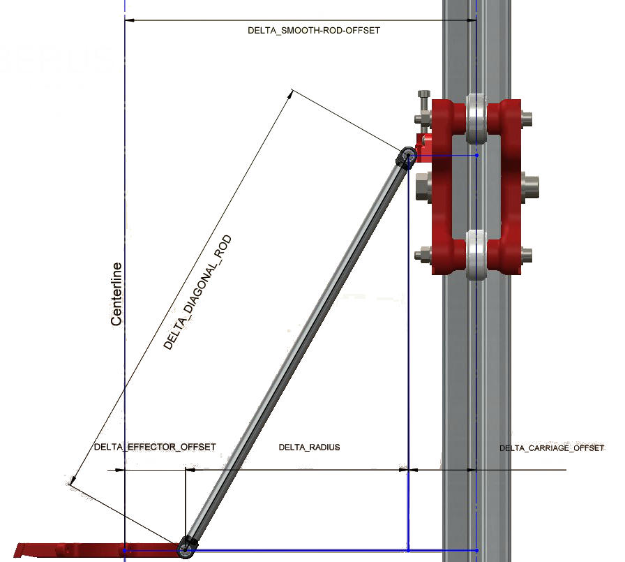
DELTA_RADIUS is calculated from values set for DELTA_SMOOTH_ROD_OFFSET, DELTA_EFFECTOR_OFFSET, and DELTA_CARRIAGE_OFFSET in configuration.h. These values are set by directly measuring their lengths on the printer.
DELTA_RADIUS = DELTA_SMOOTH_ROD_OFFSET - DELTA_EFFECTOR_OFFSET - DELTA_CARRIAGE_OFFSET
From DELTA_RADIUS we can calculate the x and y position of the three carriages on the towers:
delta_tower1_x = DELTA_RADIUS * cos(210)
               = DELTA_RADIUS * cos(180 + 30)
               = - DELTA_RADIUS * cos(30)
               = - DELTA_RADIUS * sin(60)
delta_tower1_y = DELTA_RADIUS * sin(210)
               = DELTA_RADIUS * sin(270 - 60)
               = - DELTA_RADIUS * cos(60)
delta_tower2_x = DELTA_RADIUS * cos(330)
               = DELTA_RADIUS * cos(30)
               = DELTA_RADIUS * sin(60)
delta_tower2_y = DELTA_RADIUS * sin(330)
               = - DELTA_RADIUS * sin(30)
               = - DELTA_RADIUS * cos(60)
delta_tower3_x = 0
delta_tower3_y = DELTA_RADIUS
Now, to move the printer nozzle to (x, y, z), we need to use some simple trigonometry to calculate the values of Z on the three towers:
DELTA_DIAGONAL_ROD^2 = delta_tower1_z^2 + (distance of carriage on tower1 from x, y)^2
delta_tower1_z = sqrt(DELTA_DIAGONAL_ROD^2 - (delta_tower1_x - x)^2 - (delta_tower1_y - y)^2)
Taking the given z into account:
delta_tower1_z = sqrt(DELTA_DIAGONAL_ROD^2 - (delta_tower1_x - x)^2 - (delta_tower1_y - y)^2) + z
Similarly:
delta_tower2_z = sqrt(DELTA_DIAGONAL_ROD^2 - (delta_tower2_x - x)^2 - (delta_tower2_y - y)^2) + z
delta_tower3_z = sqrt(DELTA_DIAGONAL_ROD^2 - (delta_tower3_x - x)^2 - (delta_tower3_y - y)^2) + z
Once the delta heights are calculated, it is only a matter of asking the stepper motors to move the carriages to those heights:
planner.buffer_line(delta_tower1_z, delta_tower2_z, delta_tower3_z, target[E_AXIS], feedrate_mm_s, active_extruder);
Note:
- The marlin source code actually uses delta[X_AXIS] instead of delta_tower1_z.
- We don’t need to take the height of the nozzle into consideration because we calibrate the printer such that the tip of the nozzle is actually z=0. So all z calculations are performed from the nozzle tip.