
Ever wondered how the modern flashlight works? What happens when you click the switch on, or click it multiple times to change the brightness? I was curious about it as well, so I deconstructed a commercially available flashlight (Astrolux S1) and studied the parts; even reprogrammed it to have different levels of brightness. Here is what I found out.
Parts of a flashlight
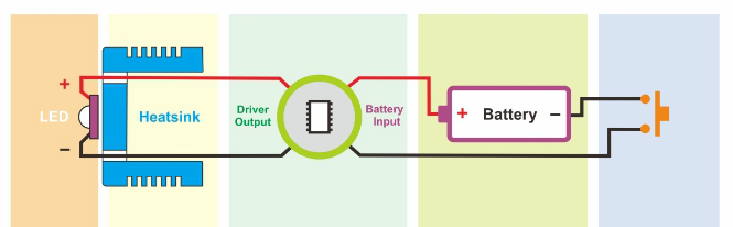
The flashlight has several parts as shown below. Many of the components like the reflector, body, glass, etc are mechanical and are not really interesting for this article. The components that really define the behavior of the flashlight is its switch, battery, driver board & the LED. We’ll look at these in detail.

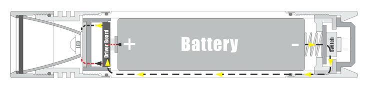
Current from the batteries is controlled by the power switch. When turned to ON, the switch completes a connection between the negative end of the batteries and the body of the flashlight where the electricity travels up to the head of the flashlight causing a difference in potential that is used to power the LED.
The difference in potential or voltage drop across an LED is also called its forward voltage (Vf). It tells you how many volts are needed to light it up. For example, a typical Cree XM-L LED has a “forward voltage” (Vf) of about 3.5 V. That is, as long as there is enough current through the LED to turn it on, the voltage across the LED is about 3.5 V. Given this, at any LED drive current, we know the LEDs approximate power consumption. If we drive the XM-L at 2 A, the LED is consuming 2 x 3.5 = 7 W.
If the voltage across the LED is constant, the brightness of the LED is then defined by the current flowing through it. By controlling the current, we can change the brightness/mode of the flashlight. Here is a chart of the output of the CREE XM-L LED (in Lumens) compared to its input current:

The bin of an LED is the manufacturing specifications of the LED. It denotes the range of lumens that the LED is capable of. It is specified as part of the LED model. For e.g., the U2 in CREE XM-L2 U2 denotes the bin of the LED. It does not specify color temperature or actual output, but it does give you an idea of potential lumens. Bins are generally 7% brighter than the previous bin. For instance, a U3 bin will have a 7% potential higher output compared to a U2 bin, assuming the same color temperature.
The Driver
The driver consists of the electronics that take power from the battery and send power to the LED. They amplify or reduce the voltage from the batteries to a correct, constant level for the LED and also control the amount of current that is delivered. The driver also contains the electronics that give the flashlight its user interface, including the number of modes and how those work relative to button presses.
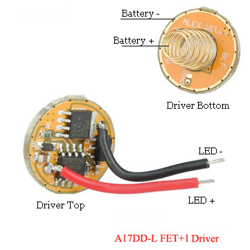
The Astrolux S1 flashlight uses an A17DD-L FET+1 driver which was developed by a group of flashlight enthusiasts in an online forum (budget Flashlight Forum, BLF). It is an opensource driver with lots of reference materials and the entire driver code available online.
Before looking at the details of A17DD-L FET + 1, lets looks at some types of drivers.
Types of Drivers
Note: For a more comprehensive list of driver types see: http://budgetlightforum.com/node/33820
Direct Drive
If the battery always supplies the correct voltage to an LED, you don’t really need a driver at all. You just need to connect the battery directly to the LED. As its name implies, Direct Driver provides a direct path to the LED, just like old incandescent flashlights. This type of driver is used by people who want to make extremely powerful flashlights. It is also used in cheap flashlights, but they add a resistor that will limit the current to a lower value.
This type of driver is quite efficient since all of the power from the battery is delivered to the LED. The disadvantage then is that the current will vary with the battery voltage as it discharges. As voltage decreases the light will dim and draw less current. If a constant brightness is desired, a driver that offers some kind of current regulation is required.
Linear Current Regulator
This is the equivalent of a direct drive flashlight with a resistor to limit current, but the resistance is constantly adjusted to make a constant current. Most Linear drivers use a 7135 chip as linear regulators. A 7135 will supply a constant 350ma current to a LED.
A Linear driver can have a number of AMC7135 current regulating chips installed. Each chip allows 350mA of current through and when wired in parallel, the current adds, so 700mA from 2 chips, 1050mA from 3 chips, and 1400mA from 4 etc. Eight 350mA chips gives 2800mA which is ideal for XM-L2 and XP-L LEDs. Constrained to a particular current, the LED will settle in at its Vf for that current and the rest of the voltage from the battery will be converted to heat by the regulator chips. By connecting different number of 7135s, we can control the current and in turn the brightness of the flashlight.
A17DD-L FET + 1 Driver
The A17DD-L FET+1 is a hybrid driver. It is a Direct Drive (DD) driver that uses a n-channel Field Effect Transistor (FET) to control current through the LED at higher modes, but it uses a 7135 for lower modes. Both the FET and 7135 is controlled by a microcontroller (ATTiny13A).
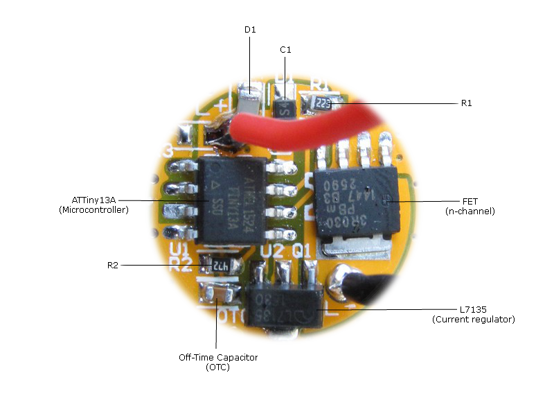
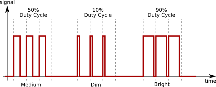
The FET is basically a switch with very low resistance. It can be rapidly turned on and off by the microprocessor using Pulse Width Modulation (PWM). See The Garage Labs explanation of PWM.
Since the FET used is n-channel, it needs to be connected in the return path of the current. i.e., from the LED – to the battery negative. When the current on the gate is large enough, the FET basically shorts the source and drain, connecting the LED- to battery negative.
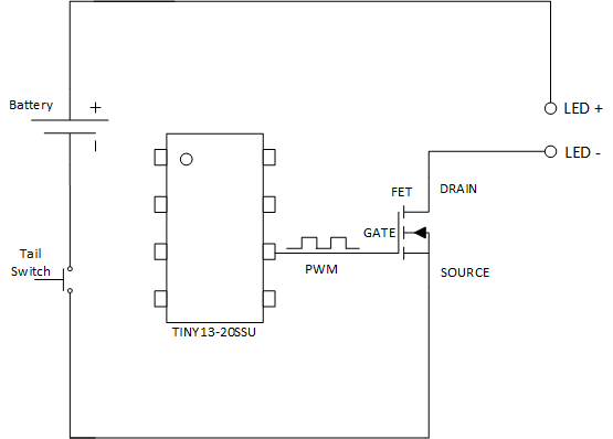
NOTE: The batteries used in AstroLux is capable of delivering very high current (>10A). The ATTiny pulls in as many mA as it needs to function, so this high amperage does not destroy the microcontroller, but when the FET source and drain is connected, it can pass all the amps that the LED can accept. So the LED is pretty much glowing the brightest whenever the FET is on. We cannot really controll the current through the LED, so we cannot control its brightness by restricting current. On the other hand, we can controll how long the LED is on by controlling the FET. By turning the LED ON & OFF rapidly, we can simulate different brightness levels. This is done using PWM on the gate.
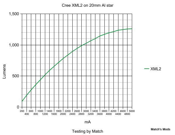
One of the issues with PWM is that it is not very efficient at low modes compared to a linear current regulator. To understand how linear regulation is more efficient than PWM, look at the graph below which shows the lumen output vs input current for a Cree XML2 LED. You can see that the graph is not linear. Consider a flashlight that produces 1000 lumens at 2800mA. Using PWM to drive the LED at 50% we get 500 lumen. But if you use a linear regulator and reduce the current by 50% (1400mA), the chart shows an output of 600 lumen, or 20% more.
For this reason, the A17DD-L FET+1 driver also adds the linear regulator (7135) so the need for PWM on lower modes is reduced. This multichannel approach lets the driver limit the current to 350mA (instead of unlimited through the FET) and use PWM as needed to work from there. Also the 350mA channel gives more uniform low levels whereas the levels from the FET vary with battery strength.
When the 7135 is on, it sinks a constant current of 350mA which gives a constant brightness. If you want to have several modes with 7135, we again have to use PWM to control 7135 on times.

By cleverly controlling how long FET and 7135 is on, we can control the brightness of the LED in each supported mode of the flashlight. For the default 7 modes supported by AstroFlux, the table below shows the output power, lumen and PWM values for both FET & 7135 and total current at the LED:
Note: This is a rough estimate as the actual values depends on battery and any flashlight mods 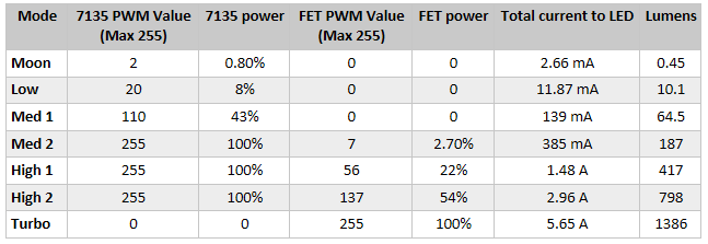
From http://budgetlightforum.com/node/41726
Voltage Measurement and Low-Voltage Protection
Quoting a guide from Texas Instruments… “Another easy way to destroy an Li-Ion battery is by discharging it too far. The Li-Ion cell should never be allowed to drop below about 2.4V, or an internal chemical reaction will occur where one of the battery electrodes can oxidize (corrode) through a process which cannot be reversed by recharging. If this occurs, battery capacity will be lost (and the cell may be completely destroyed).”
The driver needs to accurately measure the battery voltage. The driver does this by connecting a voltage divider to one of the pins on the ATTiny microcontroller. When a low voltage is detected, the microcontroller will automatically switch to a lower mode to prolong the battery life, or switch off the flashlight if the battery is dangerously low.
The R1 & R2 resistors form the voltage divider circuit that is connected to ADC pin 7 on the microcontroller. Here is how this works.
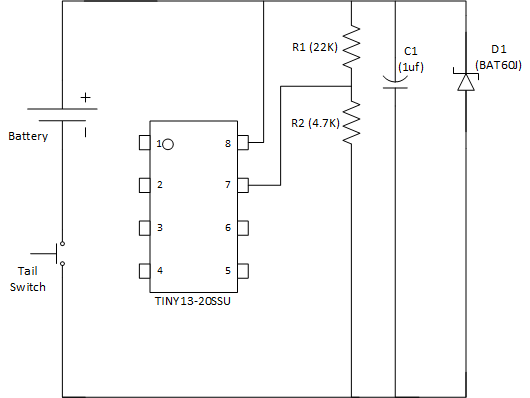
The ATTIny has an internal 1.1V reference voltage that can be used to compare and monitor the battery voltage. For this comparison to work, the battery voltage (typically 3-4V) should be dropped to a value that is near the reference voltage. This is necessary because the ADC pins (pin 7) can only measure voltages smaller or equal to the reference. This is achieved by selecting appropriate values for the R1, R2 voltage divider. The capacitor (C1) provides some smoothing while the 5.1V Zener diode (D1) provides over-voltage protection.
Here is a simple way to determine the ADC cutoff value for low voltage protection
As there usually is a diode in front of the µC to provide reverse polarity protection, V_cc to the microcontroller & voltage divider is 200mV to 600mV lower than V_bat. We will call this voltage drop V_diode.
The voltage divider consists of two resistors in series, connecting V_cc to ground. The voltage between the resistors is measured by the ADC and can be expressed by the following formula:
V_adc = V_cc * (R2 / (R1 + R2))
The ADC is set to measure with 8 bit resolution in the range from 0V to V_ref. The value returned by the ADC can be expressed by this formula:
val = 255 * (V_adc / V_ref);
By subsequently substituting V_adc and V_cc, we get the following formula:
val = ((V_bat - V_diode) * R2 * 255) / ((R1 + R2) * V_ref)
Now we can substitute the component values and the desired target voltage to get the ADC value at which the battery alert should be triggered.
For A17DD-L FET + 1:
V_diode = 0 (We don't have a reverse polarity diode)
V_ref = 1.1V
V_bat = 2.8V <= target voltage
R1 = 22kOhm
R2 = 4.7KOhm
val = ((2.8V - 0) * 4.7kOhm * 255) / ((22kOhm + 4.7kOhm) * 1.1V) = 114
A 2.8V cut-off is a balance between using as much power as possible and avoiding cell damage. There’s only like 2 or 3mAh left in the battery at that voltage, so we are not missing much. It also provides a longer window for the operator to react and click the light completely off.
Flashlight behavior when LV is detected:
- While the light is on high, voltage slowly drops to 2.7V.
- LVP kicks in and drops the output to medium.
- The battery recovers to 3.0V and runs for a while.
- Voltage eventually drops to 2.7V again, so LVP activates and puts the light into low mode.
- The battery recovers to 2.9V and runs for a while.
- Voltage drops below 2.8V again, but there is no lower level to drop to. LVP shuts the light off and enters deep sleep mode.
Off-time capacitor
There are 2 ways you can switch modes in a flashlight:
- Switch off the flashlight and quickly turn back on.
- Half-press the switch so the flashlight switches off momentarily.
In either methods, the flashlight is effectively turned off, so there is no power driving the microcontroller. How then does the microcontroller keep track of how long the flashlight was switched off?
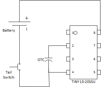
A 1uF Ceramic Capacitor connected between Pin 2 and ground allows ATTiny to detect mode change requests. This capacitor is called an Off-Time Capacitor (OTC). The ATtiny charges the OTC while the light is on. When the flashlight is off, the voltage across the capacitor decays by slowly leaking current through the microcontroller itself (which acts like a giant resistor). When the light is turned back on, the ATtiny can measure the voltage remaining in the capacitor via the ADC pin (pin 2). If the capacitor is completely drained, the flashlight has been off for a long time and ATTiny keeps the current mode it read from EEPROM. On the other hand, if there is sufficient charge in the capacitor, the flashlight was cycled quickly, so the next mode is selected and written to EEPROM.
 http://www.robotroom.com/Capacitor-Self-Discharge-2.html
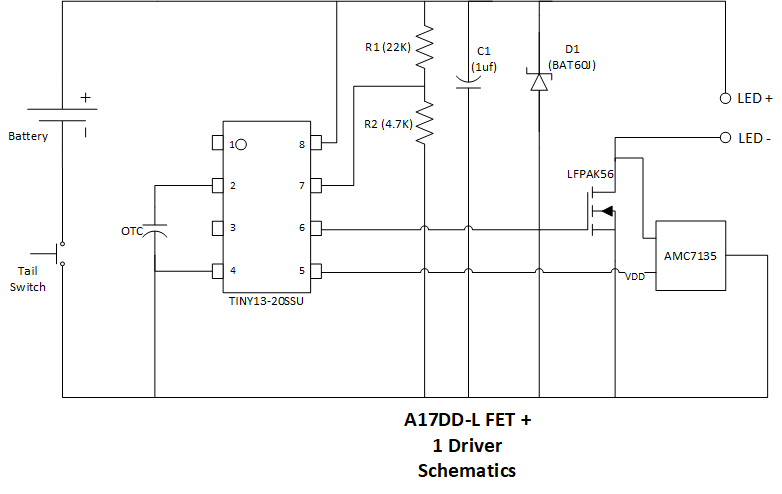
A17DD-L FET+1 Schematics
Putting all the components explained together, we arrive at the final schematics for the A17DD-l FET+1 driver.
Flashlight Firmware
There are several firmware available for this driver. One of the most famous (because it is really well written) is by Toymaker. You can find her firmware here. I have modified Toymaker’s firmware to my own liking and you can find my version on my Github here.
/*
 * Custom FET+7135 flashlight driver firmware based on the Toy Keeper's
 * generic firmware (tk-otc).
 * Expects a FET+1 style driver, supports two independent power channels.
 *
 * Copyright (C) 2015 Selene Scriven
 * Copyright (C) 2017 Deepak Kandepet
 *
 * This program is free software: you can redistribute it and/or modify
 * it under the terms of the GNU General Public License as published by
 * the Free Software Foundation, either version 3 of the License, or
 * (at your option) any later version.
 *
 * This program is distributed in the hope that it will be useful,
 * but WITHOUT ANY WARRANTY; without even the implied warranty of
 * MERCHANTABILITY or FITNESS FOR A PARTICULAR PURPOSE.  See the
 * GNU General Public License for more details.
 *
 * You should have received a copy of the GNU General Public License
 * along with this program.  If not, see <http://www.gnu.org/licenses/>.
 *
 *
 */
/******************** hardware-specific values **************************/
// ATTINY13
#define F_CPU 4800000UL
#define EEPSIZE 64
#define V_REF REFS0
#define BOGOMIPS 950
/******************** I/O pin and register layout ************************/
/*
 *         ATTINY13A
 *           ----
 *   Reset -|1  8|- VCC
 *     OTC -|2  7|- Voltage ADC
 *  Star 3 -|3  6|- PWM (FET)
 *     GND -|4  5|- PWM (1x7135)
 *           ----
 */
#define STAR2_PIN   PB0     // If this pin isn't used for ALT_PWM
#define STAR3_PIN   PB4     // pin 3
#define CAP_PIN     PB3     // pin 2, OTC
#define CAP_CHANNEL 0x03    // MUX 03 corresponds with PB3 (Star 4)
#define CAP_DIDR    ADC3D   // Digital input disable bit corresponding with PB3
#define PWM_PIN     PB1     // pin 6, FET PWM
#define PWM_LVL     OCR0B   // OCR0B is the output compare register for PB1
#define ALT_PWM_PIN PB0     // pin 5, 1x7135 PWM
#define ALT_PWM_LVL OCR0A   // OCR0A is the output compare register for PB0
#define VOLTAGE_PIN PB2     // pin 7, voltage ADC
#define ADC_CHANNEL 0x01    // MUX 01 corresponds with PB2
#define ADC_DIDR    ADC1D   // Digital input disable bit corresponding with PB2
#define ADC_PRSCL   0x06    // clk/64
/******************* PWM *****************************/
//#define FAST 0x23           // fast PWM channel 1 only
//#define PHASE 0x21          // phase-correct PWM channel 1 only
#define FAST 0xA3           // fast PWM both channels
#define PHASE 0xA1          // phase-correct PWM both channels
// output to use for blinks on battery check mode (primary PWM level, alt PWM level)
#define BLINK_BRIGHTNESS    0,20
// Mode group
#define NUM_MODES           3
// PWM levels for the FET
#define FET_LEVELS             0,7,137 // Turbo mode (255) is a special mode defined below
// PWM levels for the small circuit (1x7135)
#define LM7135_LEVELS             3,110,255
// PWM speed for each mode
#define PWM_MODES           PHASE,FAST,FAST
#define NUM_SPECIAL_MODES          4
#define SPECIALMODES         TURBO,STROBE,BIKING_STROBE,BATTCHECK
#define SPECIALMODES_PWM_MODES     PHASE,PHASE,PHASE,PHASE
#define SPECIALMODES_LM7135_LEVELS     0,0,0,0   // Zeroes, same length as NUM_SPECIAL_MODES
#define TURBO     255       // Convenience code for turbo mode (has to be unsigned byte)
#define BATTCHECK 254       // Convenience code for battery check mode
#define STROBE    253       // Convenience code for strobe mode
#define BIKING_STROBE 252   // Convenience code for biking strobe mode
#define BLINK_SPEED 500
// How many timer ticks before before dropping down.
// Each timer tick is 500ms, so "60" would be a 30-second stepdown.
// Max value of 255 unless you change "ticks"
#define TURBO_TIMEOUT 90 // only for testing
/********************** Voltage ADC calibration **************************/
// Calibration values for voltage and OTC
// These values were measured using RMM's FET+7135.
// See battcheck/readings.txt for reference values.
// These are the ADC values we expect for specific voltages
#define ADC_44     194
#define ADC_43     189
#define ADC_42     184
#define ADC_41     178
#define ADC_40     173
#define ADC_39     168
#define ADC_38     163
#define ADC_37     158
#define ADC_36     152
#define ADC_35     147
#define ADC_34     142
#define ADC_33     137
#define ADC_32     131
#define ADC_31     126
#define ADC_30     121
#define ADC_29     116
#define ADC_28     111
#define ADC_27     105
#define ADC_26     100
#define ADC_25     95
#define ADC_24     90
#define ADC_23     84
#define ADC_22     79
#define ADC_21     74
#define ADC_20     69
#define ADC_100p   ADC_42  // the ADC value for 100% full (resting)
#define ADC_75p    ADC_40  // the ADC value for 75% full (resting)
#define ADC_50p    ADC_38  // the ADC value for 50% full (resting)
#define ADC_25p    ADC_35  // the ADC value for 25% full (resting)
#define ADC_0p     ADC_30  // the ADC value for 0% full (resting)
#define ADC_LOW    ADC_30  // When do we start ramping down
#define ADC_CRIT   ADC_27  // When do we shut the light off
/********************** Offtime capacitor calibration ********************/
// Values are between 1 and 255, and can be measured with offtime-cap.c
// See battcheck/otc-readings.txt for reference values.
// These #defines are the edge boundaries, not the center of the target.
#ifdef USE_MEDIUM_PRESS
// The OTC value 0.5s after being disconnected from power
// (anything higher than this is a "short press")
#define CAP_SHORT           190
// The OTC value 1.5s after being disconnected from power
// Between CAP_MED and CAP_SHORT is a "medium press"
#define CAP_MED             94
// Below CAP_MED is a long press
#else
// The OTC value 1.0s after being disconnected from power
// Anything higher than this is a short press, lower is a long press
#define CAP_SHORT           115
#endif
// Ignore a spurious warning, we did the cast on purpose
#pragma GCC diagnostic ignored "-Wint-to-pointer-cast"
#include <avr/pgmspace.h>
#include <avr/eeprom.h>
#include <avr/sleep.h>
#include <util/delay_basic.h>
// Having own _delay_ms() saves some bytes AND adds possibility to use variables as input
void _delay_ms(uint16_t n)
{
    while(n-- > 0) _delay_loop_2(BOGOMIPS);
}
void _delay_s()  // because it saves a bit of ROM space to do it this way
{
    _delay_ms(1000);
}
inline void ADC_on() {
    // disable digital input on ADC pin to reduce power consumption
    DIDR0 |= (1 << ADC_DIDR);
    // 1.1v reference, left-adjust, ADC1/PB2
    ADMUX  = (1 << V_REF) | (1 << ADLAR) | ADC_CHANNEL;
    // enable, start, prescale
    ADCSRA = (1 << ADEN ) | (1 << ADSC ) | ADC_PRSCL;
}
uint8_t get_voltage() {
    // Start conversion
    ADCSRA |= (1 << ADSC);
    // Wait for completion
    while (ADCSRA & (1 << ADSC));
    // Send back the result
    return ADCH;
}
/* Battery voltage to blinks mapping for battery check.
 * We use 18350/18650 with voltage of 3.7v.
 *  #   186 - 4.00V - 183
 *  #   176 - 3.80V - 173
 *  #   169 - 3.64V
 *  #   162 - 3.50V - 160
 *  #   160 - 3.45V
 *  #   138 - 3.00V - 137
 *  #   134 - 2.90V - 132
 *  #   129 - 2.80V - 127
 *  #   124 - 2.70V - 123
 */
PROGMEM const uint8_t voltage_blinks[] = {
               // 0 blinks for less than 1%
    ADC_30,    // 1 blink  for 1%-12.5% (~2.7v)
    ADC_33,    // 2 blinks for 12.5%-25% (~2.8v)
    ADC_35,    // 3 blinks for 25%-37.5% (~2.9v)
    ADC_37,    // 4 blinks for 37.5%-50% (~3.0v)
    ADC_38,    // 5 blinks for 50%-62.5% (~3.45v)
    ADC_39,    // 6 blinks for 62.5%-75% (~3.5v)
    ADC_40,    // 7 blinks for 75%-87.5% (~3.64v)
    ADC_41,    // 8 blinks for 87.5%-100% (~3.80v)
    ADC_42,    // 9 blinks for >100% (~4.0v)
    255,       // Ceiling, don't remove  (10 blinks means "error")
};
inline uint8_t battcheck() {
    // Return an int, number of "blinks", for approximate battery charge
    // Uses the table above for return values
    uint8_t i, voltage;
    voltage = get_voltage();
    // figure out how many times to blink
    for (i=0;
         voltage > pgm_read_byte(voltage_blinks + i);
         i ++) {}
    return i;
}
// Global config / state variables
uint8_t eepos = 0;         // EEPROM read/write position
uint8_t memory = 1;        // == 1 remember last mode,
                           // == 0 start at moonlight mode
uint8_t mode_idx = 0;      // current or last-used mode number
// number of regular non-special modes in mode group
#define SOLID_MODES NUM_MODES
// total length of mode group's array
#define MODE_COUNT SOLID_MODES+NUM_SPECIAL_MODES
// Modes (gets set when the light starts up based on saved config values)
// NOTE: SPECIALMODES only has special codes, the actual level for each special
// mode is set in code.
PROGMEM const uint8_t fet_levels[] = { FET_LEVELS, SPECIALMODES };
PROGMEM const uint8_t lm7135_levels[] = { LM7135_LEVELS, SPECIALMODES_LM7135_LEVELS };
PROGMEM const uint8_t pwm_modes[] = { PWM_MODES, SPECIALMODES_PWM_MODES };
void save_state() {  // central method for writing (with wear leveling)
    // a single 16-bit write uses less ROM space than two 8-bit writes
    uint8_t eep;
    uint8_t oldpos=eepos;
    eepos = (eepos+1) & (EEPSIZE-1);  // wear leveling, use next cell
    eep = mode_idx;
    eeprom_write_byte((uint8_t *)(eepos), eep);      // save current state
    eeprom_write_byte((uint8_t *)(oldpos), 0xff);    // erase old state
}
void restore_state() {
    uint8_t eep;
    // find the config data
    for(eepos=0; eepos<EEPSIZE; eepos++) {
        eep = eeprom_read_byte((const uint8_t *)eepos);
        if (eep != 0xff) break;
    }
    // unpack the config data
    if (eepos < EEPSIZE) {
        mode_idx = eep;
    }
    // unnecessary, save_state handles wrap-around
    // (and we don't really care about it skipping cell 0 once in a while)
    //else eepos=0;
}
inline void next_mode() {
    mode_idx += 1;
    //if (mode_idx >= SOLID_MODES) {
    if (mode_idx >= MODE_COUNT) {
        // Wrap around
        mode_idx = 0;
    }
}
inline void prev_mode() {
    if (mode_idx > 0) {
        mode_idx -= 1;
    } else {
        // Otherwise, wrap around (this allows entering special modes)
        mode_idx = MODE_COUNT - 1;
    }
}
void set_output(uint8_t pwm1, uint8_t pwm2) {
    // Need PHASE to properly turn off the light
    if ((pwm1==0) && (pwm2==0)) {
        TCCR0A = PHASE;
    }
    PWM_LVL = pwm1;
    ALT_PWM_LVL = pwm2;
}
void set_mode(uint8_t mode) {
    TCCR0A = pgm_read_byte(pwm_modes + mode);
    set_output(pgm_read_byte(fet_levels + mode), pgm_read_byte(lm7135_levels + mode));
}
void blink(uint8_t val)
{
    for (; val>0; val--)
    {
        set_output(BLINK_BRIGHTNESS);
        _delay_ms(BLINK_SPEED / 5);
        set_output(0,0);
        _delay_ms(BLINK_SPEED * 4 / 5);
    }
}
int main(void)
{
    uint8_t cap_val;
    // Read the off-time cap *first* to get the most accurate reading
    // Start up ADC for capacitor pin
    DIDR0 |= (1 << CAP_DIDR);                           // disable digital input on ADC pin to reduce power consumption
    ADMUX  = (1 << V_REF) | (1 << ADLAR) | CAP_CHANNEL; // 1.1v reference, left-adjust, ADC3/PB3
    ADCSRA = (1 << ADEN ) | (1 << ADSC ) | ADC_PRSCL;   // enable, start, prescale
    // Wait for completion
    while (ADCSRA & (1 << ADSC));
    // Start again as datasheet says first result is unreliable
    ADCSRA |= (1 << ADSC);
    // Wait for completion
    while (ADCSRA & (1 << ADSC));
    cap_val = ADCH; // save this for later
    // All ports default to input, but turn pull-up resistors on for the stars (not the ADC input!  Made that mistake already)
    // only one star, because one is used for PWM channel 2
    // and the other is used for the off-time capacitor
    PORTB = (1 << STAR3_PIN);
    // Set PWM pin to output
    DDRB |= (1 << PWM_PIN);     // enable main channel
    DDRB |= (1 << ALT_PWM_PIN); // enable second channel
    // Set timer to do PWM for correct output pin and set prescaler timing
    //TCCR0A = 0x23; // phase corrected PWM is 0x21 for PB1, fast-PWM is 0x23
    //TCCR0B = 0x01; // pre-scaler for timer (1 => 1, 2 => 8, 3 => 64...)
    TCCR0A = PHASE;
    // Set timer to do PWM for correct output pin and set prescaler timing
    TCCR0B = 0x01; // pre-scaler for timer (1 => 1, 2 => 8, 3 => 64...)
    // Read config values and saved state
    restore_state();
    if (cap_val > CAP_SHORT) {
        // Indicates they did a short press, go to the next mode
        next_mode(); // Will handle wrap arounds
#ifdef USE_MEDIUM_PRESS
    } else if (cap_val > CAP_MED) {
        // User did a medium press, go back one mode
        prev_mode(); // Will handle "negative" modes and wrap-arounds
#endif
    } else {
        // Long press, keep the same mode
        // ... or reset to the first mode
        if (! memory) {
            // Reset to the first mode
            mode_idx = 0;
        }
    }
    save_state();
    // Turn off ADC
    //ADC_off();
    // Charge up the capacitor by setting CAP_PIN to output
    DDRB  |= (1 << CAP_PIN);    // Output
    PORTB |= (1 << CAP_PIN);    // High
    // Turn features on or off as needed
    ADC_on();
    //ACSR   |=  (1<<7); //AC off
    uint8_t output;
    uint8_t ticks = 0;
    // Voltage Mon
    uint8_t lowbatt_cnt = 0;
    uint8_t i = 0;
    uint8_t voltage;
    // Make sure voltage reading is running for later
    ADCSRA |= (1 << ADSC);
    while(1) {
        output = pgm_read_byte(fet_levels + mode_idx);
        if (output == STROBE) {
            // 10Hz tactical strobe
            set_output(255,0);
            _delay_ms(50);
            set_output(0,0);
            _delay_ms(50);
        }
        else if (output == BIKING_STROBE) {
            // 2-level stutter beacon for biking and such
            // normal version
            for(i=0;i<4;i++) {
                set_output(255,0);
                _delay_ms(5);
                set_output(0,255);
                _delay_ms(65);
            }
            _delay_ms(720);
        }
        // Check Battery status
        else if (output == BATTCHECK) {
            blink(battcheck());
            // wait between readouts
            _delay_s(); _delay_s();
        }
        else {  // Regular non-special solid mode
            set_mode(mode_idx);
            // Track if and for how long we are in turbo mode and drop down smartly.
            // Do some magic here to handle turbo step-down
            //if (ticks < 255) ticks++;  // don't roll over
            ticks ++;  // actually, we don't care about roll-over prevention
            if ((ticks > TURBO_TIMEOUT)
                    && (output == TURBO)) {
                //mode_idx = SOLID_MODES - 2; // step down to second-highest mode
                //Step down to whatever is the previous mode
                prev_mode();
                set_mode(mode_idx);
                save_state();
            }
            // Otherwise, just sleep.
            _delay_ms(500);
        }
        // Voltage Monitoring
        if (ADCSRA & (1 << ADIF)) {  // if a voltage reading is ready
            voltage = ADCH; // get_voltage();
            // See if voltage is lower than what we were looking for
            //if (voltage < ((mode_idx <= 1) ? ADC_CRIT : ADC_LOW)) {
            if (voltage < ADC_LOW) {
                lowbatt_cnt ++;
            } else {
                lowbatt_cnt = 0;
            }
            // See if it's been low for a while, and maybe step down
            if (lowbatt_cnt >= 8) {
                // DEBUG: blink on step-down:
                //set_output(0,0);  _delay_ms(100);
                i = mode_idx; // save space by not accessing mode_idx more than necessary
                // properly track special vs normal modes
                if (i >= SOLID_MODES) {
                    // step down from blinky modes to medium
                    i = 2;
                } else if (i > 0) {
                    // step down from solid modes one at a time
                    i -= 1;
                } else { // Already at the lowest mode
                    i = 0;
                    // Turn off the light
                    set_output(0,0);
                    // Power down as many components as possible
                    set_sleep_mode(SLEEP_MODE_PWR_DOWN);
                    sleep_mode();
                }
                set_mode(i);
                mode_idx = i;
                save_state();
                lowbatt_cnt = 0;
                // Wait at least 2 seconds before lowering the level again
                _delay_ms(250);  // this will interrupt blinky modes
            }
            // Make sure conversion is running for next time through
            ADCSRA |= (1 << ADSC);
        }
        //sleep_mode();  // incompatible with blinky modes
    }
    //return 0; // Standard Return Code
}
To actually burn the firmware to ATTiny you need to connect an USB ASP programmer to the ATTiny on the driver. Flashlight wiki has a comprehensive set of instructions for creating your own programmer and all the software needed to burn the firmware.
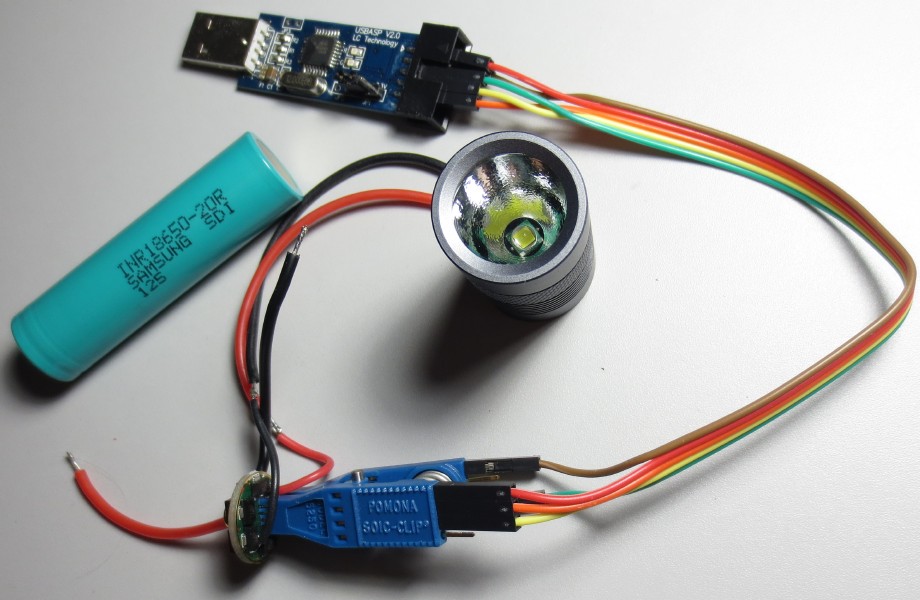
Once you have your programmer ready, you can use AVRDude to write the hex file to ATTIny and enjoy.
Testing if avrdude can communicate with ATTiny
>avrdude -p t13 -c usbasp -n
avrdude: warning: cannot set sck period. please check for usbasp firmware update. avrdude: AVR device initialized and ready to accept instructions
Reading | ################################################## | 100% 0.02s
avrdude: Device signature = 0x1e9007 avrdude: current erase-rewrite cycle count is -65025 (if being tracked)
avrdude: safemode: Fuses OK
avrdude done. Thank you.
Writing the firmware
>avrdude -c usbasp -p t13 -u -Uflash:w:dk-a17dd.hex -Ulfuse:w:0x75:m -Uhfuse:w:0xfd:m
avrdude: warning: cannot set sck period. please check for usbasp firmware update. avrdude: AVR device initialized and ready to accept instructions
Reading | ################################################## | 100% 0.02s
avrdude: Device signature = 0x1e9007 avrdude: NOTE: FLASH memory has been specified, an erase cycle will be performed To disable this feature, specify the -D option. avrdude: erasing chip
avrdude: warning: cannot set sck period. please check for usbasp firmware update. avrdude: reading input file "dk-a17dd.hex" avrdude: input file dk-a17dd.hex auto detected as Intel Hex
avrdude: writing flash (708 bytes):
Writing | ################################################## | 100% 0.52s
avrdude: 708 bytes of flash written avrdude: verifying flash memory against dk-a17dd.hex: avrdude: load data flash data from input file dk-a17dd.hex: avrdude: input file dk-a17dd.hex auto detected as Intel Hex avrdude: input file dk-a17dd.hex contains 708 bytes avrdude: reading on-chip flash data:
Reading | ################################################## | 100% 0.35s
avrdude: verifying ... avrdude: 708 bytes of flash verified avrdude: reading input file "0x75" avrdude: writing lfuse (1 bytes):
Writing | ################################################## | 100% 0.02s
avrdude: 1 bytes of lfuse written avrdude: verifying lfuse memory against 0x75: avrdude: load data lfuse data from input file 0x75: avrdude: input file 0x75 contains 1 bytes avrdude: reading on-chip lfuse data:
Reading | ################################################## | 100% 0.00s
avrdude: verifying ... avrdude: 1 bytes of lfuse verified avrdude: reading input file "0xfd" avrdude: writing hfuse (1 bytes):
Writing | ################################################## | 100% 0.02s
avrdude: 1 bytes of hfuse written avrdude: verifying hfuse memory against 0xfd: avrdude: load data hfuse data from input file 0xfd: avrdude: input file 0xfd contains 1 bytes avrdude: reading on-chip hfuse data:
Reading | ################################################## | 100% 0.00s
avrdude: verifying ... avrdude: 1 bytes of hfuse verified
avrdude done. Thank you.
You said “Toymaker” instead of “ToyKeeper” in that last section.
Hi there. This was the first web page I checked out wanting to learn about drivers for my new flashlight addiction. Being an old electronic specialist all this made perfect sense to me and I loved it. I even caught one wrong word about monsters . I will check the other links out. Tnx much for your knowledge and ability to teach it. Regards, Doug E.